Part 1: Examine the Header Fields in an Ethernet II Frame
In Part 1, examine the header fields and content in an Ethernet II frame using a Wireshark capture before analyzing local and remote ping traffic in Part 2.
Step 1: Review the Ethernet II header field descriptions and lengths
| Preamble | Destination Address | Source Address | Frame Type | Data | FCS |
|---|---|---|---|---|---|
| 8 bytes | 6 bytes | 6 bytes | 2 bytes | 46–1500 bytes | 4 bytes |
The preamble (7 bytes of alternating 1010 plus 1-byte SFD) and FCS are not shown in Wireshark’s detail pane; the NIC handles both in hardware.
Step 2: Examine the network configuration of the PC
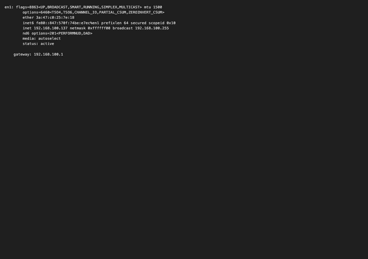
Active interface: Wi‑Fi en1. Host IPv4 192.168.100.137/24, default gateway 192.168.100.1. MAC seen on the LAN during capture: 3a:47:c0:25:7e:18 (macOS private Wi‑Fi address; hardware MAC d0:11:e5:72:1a:17).
Step 3: Examine Ethernet frames in a Wireshark capture
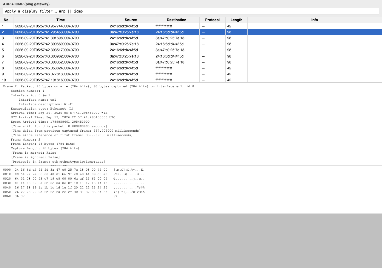
Apply filter arp || icmp. Typical order after ping to the default gateway: ARP request → ARP reply → ICMP Echo request/reply pairs. Capture files: tugas/lab-gateway.pcapng, tugas/lab-arp-icmp.pcapng.
Step 4: Examine the Ethernet II header contents of an ARP request
| Field | Value | Description |
|---|---|---|
| Preamble | Not shown in capture | Synchronization bits; processed by the NIC before the frame is delivered to the host. |
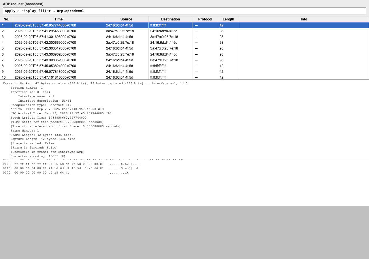
| Destination Address | ff:ff:ff:ff:ff:ff (broadcast) | 48-bit Layer 2 address. Broadcast so every host on the LAN receives the ARP frame; the host with the requested IPv4 address replies. |
| Source Address | 3a:47:c0:25:7e:18 | Unicast MAC of this PC’s Wi‑Fi NIC (sender of the ARP request for the gateway). |
| Frame Type | 0x0806 | Ethernet II type ARP. Another common value is 0x0800 (IPv4). |
| Data | ARP | ARP payload (who-has / is-at). Ethernet data field is 46–1500 bytes. |
| FCS | Not shown in capture | Frame Check Sequence; computed by the sender and checked by the receiver for transmission errors. |
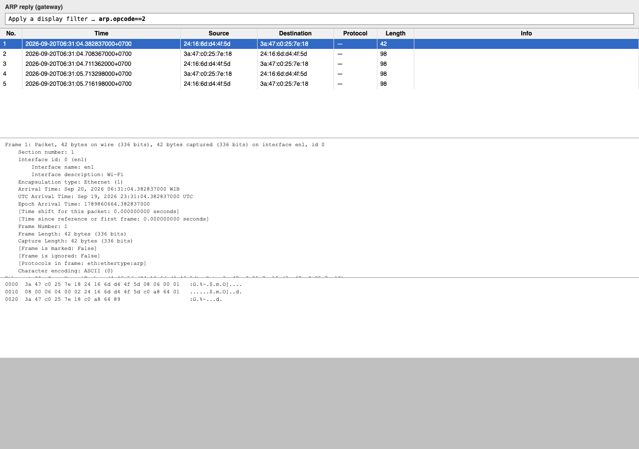
ARP reply from the gateway: source 24:16:6d:d4:4f:5d, unicast destination 3a:47:c0:25:7e:18, type 0x0806.
What is significant about the contents of the destination address field?
The destination is the Ethernet broadcast address ff:ff:ff:ff:ff:ff. Every host on the LAN receives the frame; the host whose IPv4 address is requested in the ARP payload (here the default gateway 192.168.100.1) responds with a unicast ARP reply.
Why does the PC send out a broadcast ARP prior to sending the first ping request?
The PC knows the gateway’s IP address but must learn its MAC address to build the Ethernet header for the first ICMP echo request. The ARP broadcast asks which host on the local segment owns 192.168.100.1.
What is the MAC address of the source in the first frame?
3a:47:c0:25:7e:18 — source MAC on the first ARP request frame from this PC (Wi‑Fi NIC en1).
What is the Vendor ID (OUI) of the Source NIC in the ARP reply?
Huawei (HUAWEI TECHNOLOGIES CO., LTD) — OUI 24:16:6d on the gateway NIC in the ARP reply (source 24:16:6d:d4:4f:5d).
What portion of the MAC address is the OUI?
The first three octets (24 bits) — for example 24:16:6d.
What is the NIC serial number of the source?
In the ARP reply the source is the gateway; the last three octets of the MAC are d4:4f:5d.
Part 2: Use Wireshark to Capture and Analyze Ethernet Frames
In Part 2, capture local and remote Ethernet frames, then examine the frame header fields. Remote capture (ping www.cisco.com) is Step 7.
Steps 1–5: Capture a ping to the default gateway
- Step 1. Determine the default gateway from ifconfig / ipconfig (see Part 1, Step 2).
- Step 2. Start capturing on Wi‑Fi interface en1.
- Step 3. In Wireshark, apply display filter icmp (display only; capture is unchanged).
- Step 4. From a terminal, run ping 192.168.100.1.
- Step 5. Stop capturing. File: tugas/lab-gateway.pcapng.
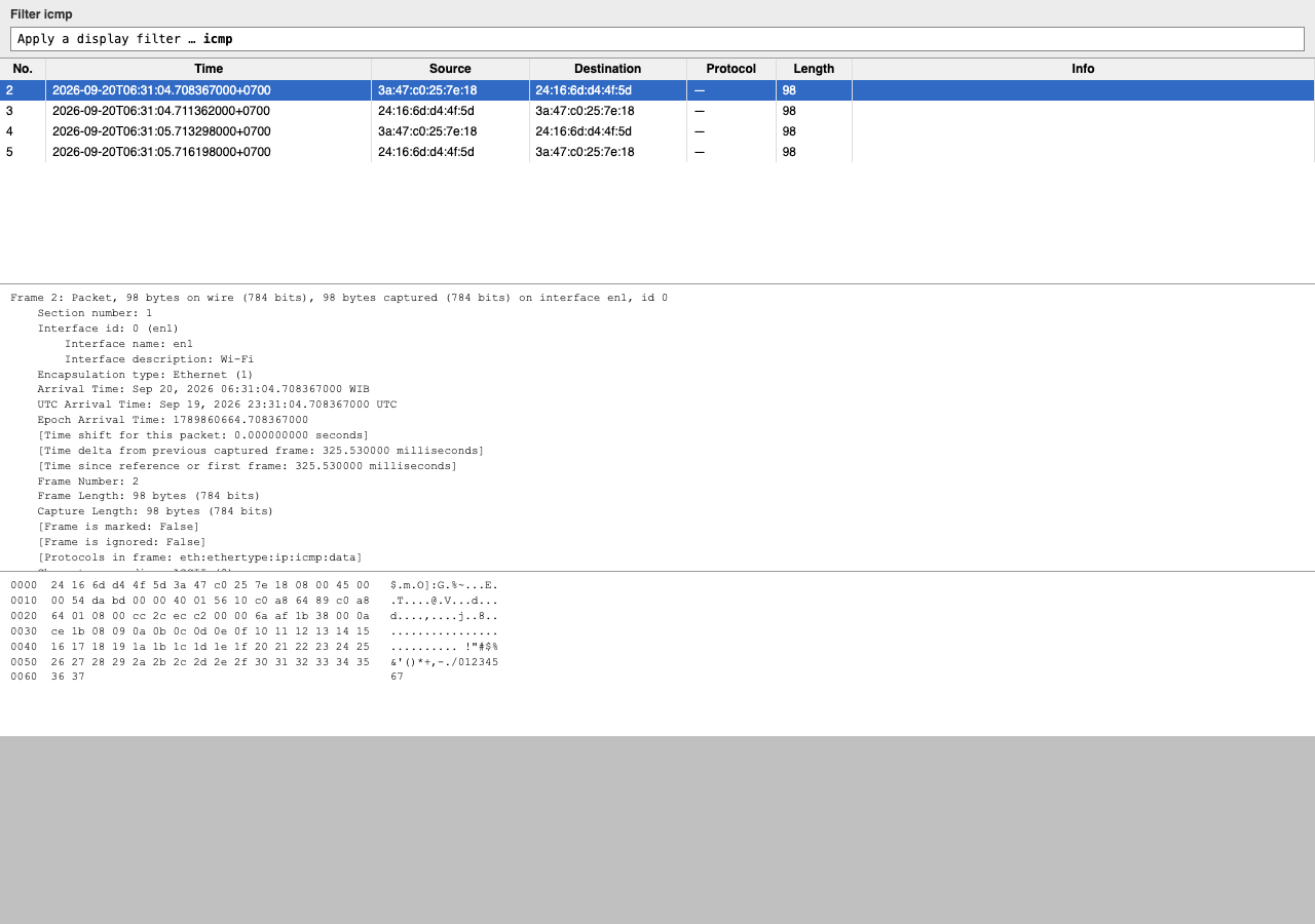
Step 6: Examine the first Echo (ping) request in Wireshark
Select the first Echo request in the packet list. Answers below follow substeps 6a–6g in the lab PDF.
What is the IP address of the PC default gateway? (Part 2, Step 1)
192.168.100.1
What is the length of the frame? (Step 6b)
98 bytes — frame 2 in lab-gateway.pcapng (first Echo request after the icmp filter).
What is the MAC address of the PC NIC? (Step 6c)
3a:47:c0:25:7e:18
What is the default gateway’s MAC address?
24:16:6d:d4:4f:5d
What type of frame is displayed? (Step 6d)
Ethernet II, type 0x0800 (IPv4).
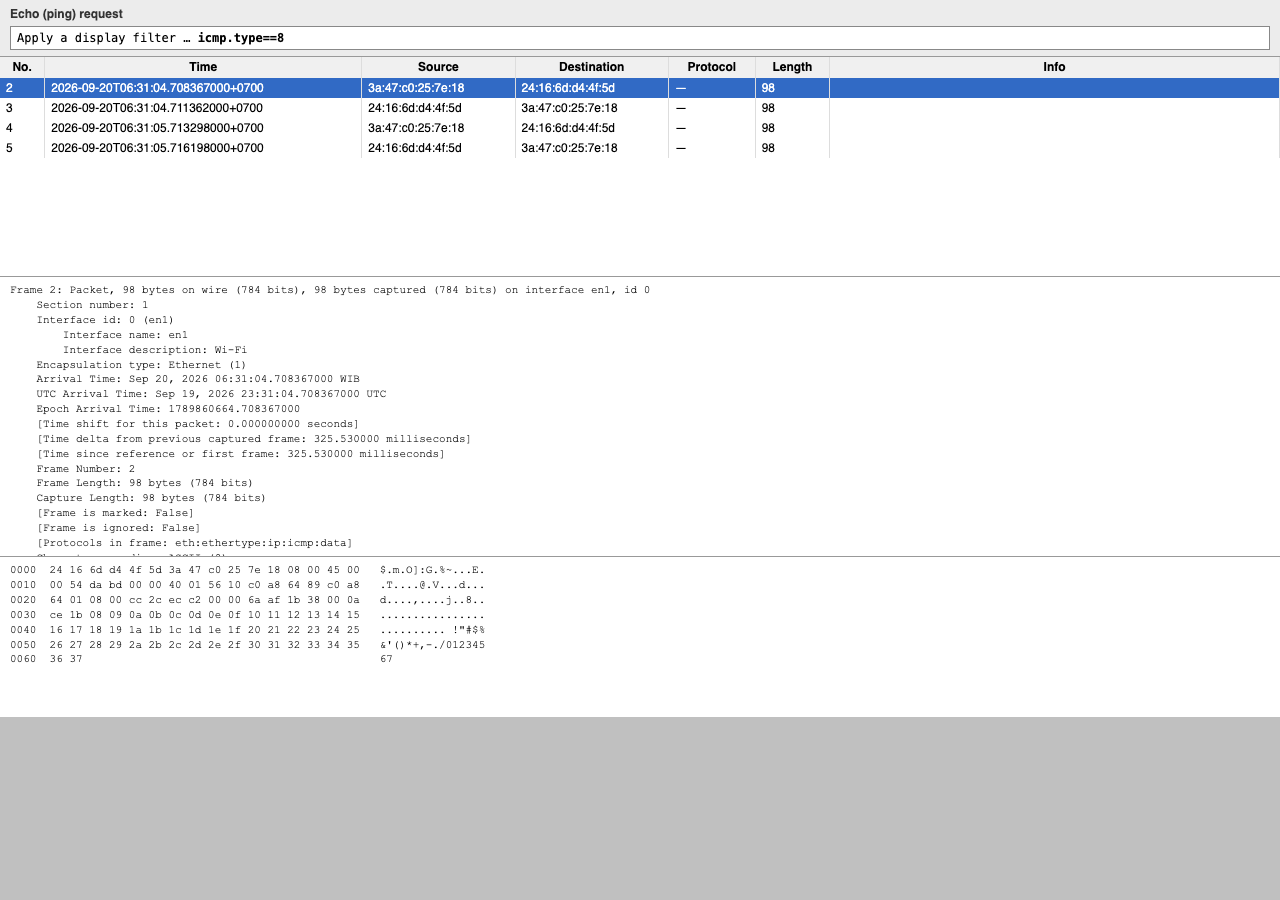
What is the source IP address? (Step 6e)
192.168.100.137
What is the destination IP address?
192.168.100.1
What do the last two highlighted octets spell? (Step 6f)
On this macOS capture the last two highlighted octets are ASCII 6 and 7 (hex 36 37). The Cisco Windows lab uses a 32-byte alphabetic ping payload; the last two letters are typically hi.
What device and MAC address is displayed as the destination address? (Step 6g)
This PC (the host); destination MAC 3a:47:c0:25:7e:18. Source and destination MACs are reversed compared with the echo request because the reply is sent by the gateway.
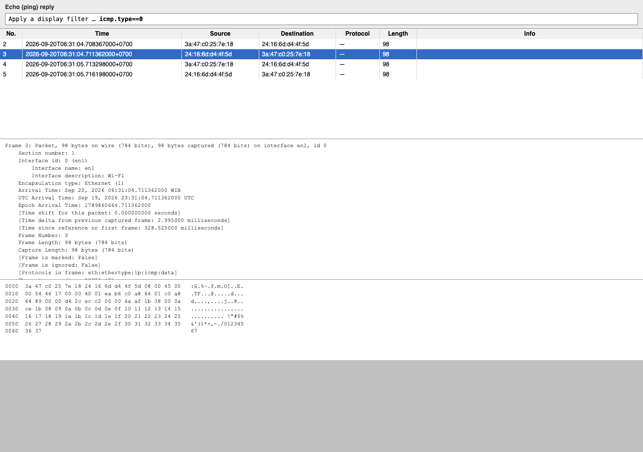
Step 7: Capture packets for a remote host
Start a new capture, run ping www.cisco.com, then stop. File: tugas/lab-icmp-remote.pcapng. The next three questions refer to the first echo request in this capture (Step 7d).
In the first echo (ping) request frame, what are the source and destination MAC addresses? (Step 7d)
Source: 3a:47:c0:25:7e:18
Destination: 24:16:6d:d4:4f:5d (default gateway — same as the local ping).
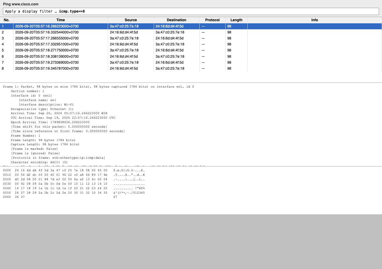
What are the source and destination IP addresses contained in the data field of the frame?
Source: 192.168.100.137
Destination: 23.75.213.45 (www.cisco.com
resolved via Akamai at capture time).
Why has the destination IP address changed, while the destination MAC address remained the same?
An Ethernet frame is delivered one hop on the LAN. For a host on another subnet, the PC still places the default gateway’s MAC in the destination field; the gateway strips the Layer 2 header, forwards the packet toward the remote IP, and each router builds a new Layer 2 header per segment.
Reflection: Wireshark does not display the preamble — what does it contain?
Seven octets of alternating 1010 bit pattern for clock synchronization, followed by one Start Frame Delimiter octet (10101011) marking the start of the frame. The NIC consumes the preamble; it is not passed up to Wireshark.
4.1–4.2 Fungsi dan karakteristik L1
ITN Module 4- Komunikasi butuh koneksi fisik (kabel/nirkabel) via NIC; performa link tidak seragam.
- L1: koneksi fisik, representasi bit → sinyal (listrik/cahaya/radio), sinkronisasi clock, topologi fisik, simplex / half-duplex / full-duplex.
- L1 menerima frame dari L2, encode ke sinyal di media — langkah terakhir encapsulation; perangkat berikutnya decode bit lalu de-encapsulate.
- Standar L1 mencakup physical components, encoding (Manchester, 4B/5B, 8B/10B), signaling (tegangan tembaga, pulsa cahaya fiber, RF wireless).
- Bandwidth (bps, K/M/G/Tbps), latency, throughput, goodput = throughput − overhead.
4.3–4.4 Media tembaga dan UTP
- Tembaga: murah, mudah dipasang; keterbatasan attenuation, EMI/RFI, crosstalk — mitigasi: batas panjang kabel, shielding, twist pair.
- UTP paling umum, konektor RJ-45; pasangan warna + twist cancel interferensi + variasi twist per foot.
- STP: shield braid/foil, lebih mahal. Koaksial: antenna wireless, cable internet premises.
- Standar kabel: TIA/EIA-568 (panjang, termination, testing); kategori IEEE (Cat5e, Cat6, …) menentukan rate Ethernet.
- UTP straight-through vs crossover (legacy); modern NIC auto-MDIX. Pinout T568A/T568B.
4.5–4.6 Fiber dan nirkabel
- Fiber: core kaca/plastik, cladding, jacket; sinyal cahaya; keunggulan jarak jauh, bandwidth tinggi, imun EMI — lebih mahal dan butuh handling hati-hati.
- Single-mode vs multimode; connector LC/SC/ST; use case backbone, campus, ISP.
- Wireless: 802.11 WLAN, seluler; shared medium, regulasi frekuensi, keamanan (WPA), interferensi dan attenuation udara/dinding.
- Pemilihan media: cost, distance, environment, bandwidth, security — sering kombinasi tembaga access + fiber backbone.